
Summary: Reduce cost by utilising existing infrastructure to provide segmentation and network isolation
Branch and WAN logical isolation has become more of a security requirement these days for both small and large enterprise as more services are run directly out of branches whether they be payment services, marketing, or day to day operations.
With this comes an increased level of security requirements to segregate traffic from various sources, there might be a requirement to have external parties access internet resources from your sites or VPN back to their own DC’s. With these requirements and increased security concerns come additional costs in operating multiple ISP, WAN circuits or physical infrastructure to seperate this traffic.
The following will walk through a design and implementation which can utilise most existing infrastructure while maintaining logical, secure separation at a branch and DC level. This might be for guest access, isolation of departments with a branch, service level guarantees, creation of private networks over public infrastructure (internet links).
Customer Problem Statement
The customer would like to separate the existing corporate branch network into two or more virtual private networks. Specifically this is for the Fixed Infrastructure Physical Surveillance data network (this is a outsourced security firm managing physical access, CCTV etc..).
- Create secure separate networks within the branch which extend all the way into the DC
- Provide the ability to limit bandwidth per network
- Provide the ability for QoS per network and as a whole
- Utilise existing infrastructure at branch sites, (consisting of Cisco 2800, 2900, 3800, 1900 routers and 6500/SUP720 series switches)
- Provide the ability to scale as required, limited only by bandwidth on WAN links and capacity on branch devices
- Support for multicast routing
- Provide the ability to extend control and administration to utilise NAC (network access control) software
- Not all networks must be part of the MPLS/VPN or DMVPN, the existing voice network should retain ‘Un-encrypted, no overlay data paths between branches and to the DC’, this meant the customer wanted to preserve the ability to route on the corporate network existing voice traffic without tunneling this.
Proposed Design
All of the above requirements can be achieved by utilising existing infrastructure, and in this case only a few sites requiring upgrade of IOS software. No hardware upgrades were required. This can be achieved through the use of DMVPN, with a little help from ‘MPLS / VRFs’ over the top to provide end-to-end separation and address portability. DMVPN on its own is not a complicated or ‘new’ technology, it has been proven over the years as a stable, reliable and easy to manage VPN technology, however the addition of MPLS / VRF’s within these tunnels provides for much greater control, flexibility, security and scale. This is also known as 25470DMVPN
2547oDMVPN aka MPLS VPN over DMVPN
This basically extends an existing MPLS VPN solution to the branch, while MPLS VPN’s are implemented at the customer DC network, the underlying transmission network (ISP, Internet) is just IP and has no knowledge of the underlying VPN’s.
This maintains the ability for the hub routers to have a single multipoint GRE tunnel interface to support large numbers of spokes. The spokes can be point-to-point or multipoint.
The WAN hub router acts as a MPLS/Layer 3VPN P router to establish the LDP neighbour relationship and label switch packet with branch routers which act as a MPL3/Layer 3VPN PE router. The single IGP process is running on the entire enterprise MAN/WAN network to enable the branch routers to establish the MP-iBGP session with RRs in the enterprise MPLS MAN network.
The following technologies will be supported over the dynamic VPN’s through the use of NHRP (Next Hop Resolution Protocol);
- IP Multicast: Supporting one-to-many and many-to-many (i.e., conferencing) communications, as required by voice, video, and data applications
- Dynamic routing protocols
- QoS: For performance and quality of voice, video, and real-time data applications
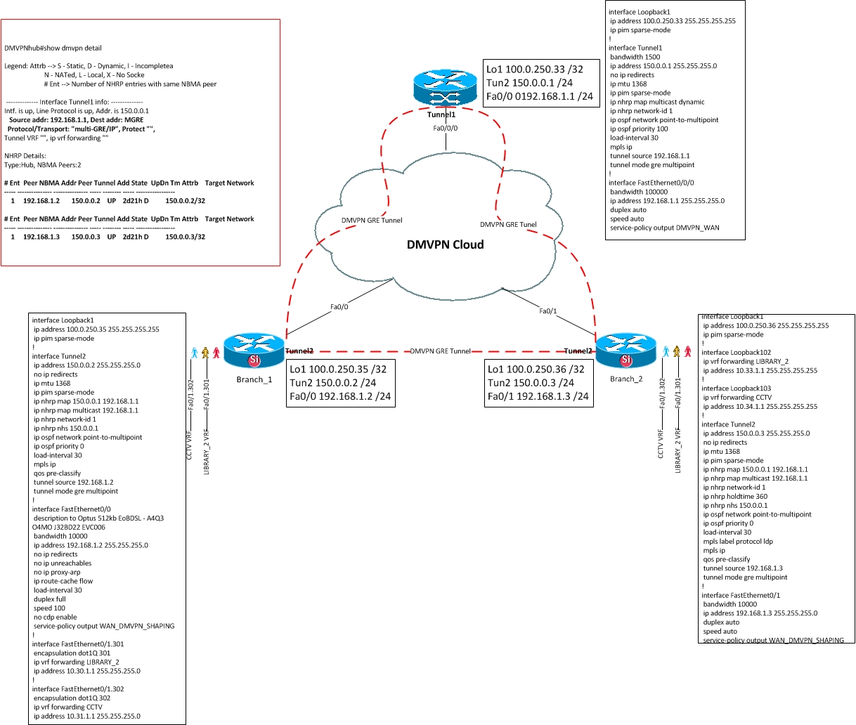
Following is a snippet for the physical connectivity for a subset of this design, two branches and one hub. The production use case was built with two hubs and multiple branches.
Configuration / Design:
- Each branch connects via a ethernet interface (this could also be serial, ATM, dialer)
- Each isolated network is contained within a sub-interface, which is tied to a single VRF
- Tunnel interfaces use NHRP to map out the hub
- Loopback interfaces are used for MPLS routing
With this configuration tunnels should establish and be routable, the individual VRF’s and isolated networks are not yet provisioned across the MPLS/VPN
The configuration for the hub routers contains the following
interface Loopback1
 ip address 100.0.250.33 255.255.255.255
 ip pim sparse-mode
!
interface Tunnel1
 bandwidth 1500
 ip address 150.0.0.1 255.255.255.0
 no ip redirects
 ip mtu 1368
 ip pim sparse-mode
 ip nhrp map multicast dynamic
 ip nhrp network-id 1
 ip ospf network point-to-multipoint
 ip ospf priority 100
 load-interval 30
 mpls ip
 tunnel source 192.168.1.1
 tunnel mode gre multipoint
!
interface FastEthernet0/0
 no ip address
 duplex auto
 speed auto
!
interface FastEthernet0/1
 no ip address
 duplex auto
 speed auto
!
interface FastEthernet0/0/0
 bandwidth 100000
 ip address 192.168.1.1 255.255.255.0
 duplex auto
 speed auto
 service-policy output DMVPN_WAN
!
router ospf 1
 mpls traffic-eng router-id Loopback1
 mpls traffic-eng area 0
 router-id 100.0.250.33
 log-adjacency-changes
 network 100.0.250.33 0.0.0.0 area 0
 network 100.0.0.0 0.0.255.255 area 0
 network 150.0.0.0 0.0.0.255 area 0
!
router ospf 100
 log-adjacency-changes
 network 192.168.1.1 0.0.0.0 area 3
!
router bgp 64512
 no synchronisation
 no bgp default route-target filter
 bgp log-neighbor-changes
 neighbour 100.0.250.35 remote-as 64512
 neighbor 100.0.250.35 update-source Loopback1
 neighbor 100.0.250.36 remote-as 64512
 neighbor 100.0.250.36 update-source Loopback1
 no auto-summary
 !
 address-family vpnv4
  neighbor 100.0.250.35 activate
  neighbor 100.0.250.35 send-community extended
  neighbor 100.0.250.35 route-reflector-client
  neighbor 100.0.250.36 activate
  neighbor 100.0.250.36 send-community extended
  neighbor 100.0.250.36 route-reflector-client
 exit-address-family
 !
ip forward-protocol nd
!
!
ip http server
no ip http secure-server
ip pim ssm range 1
!
access-list 1 permit 239.232.0.0 0.0.255.255
Each branch may have multiple tunnels for redundancy, one per hub. The hub sites will need to peer with each other to share routes for failure events etc… This can be achieved via BGP or redistribution. Following is a sample branch configuration.
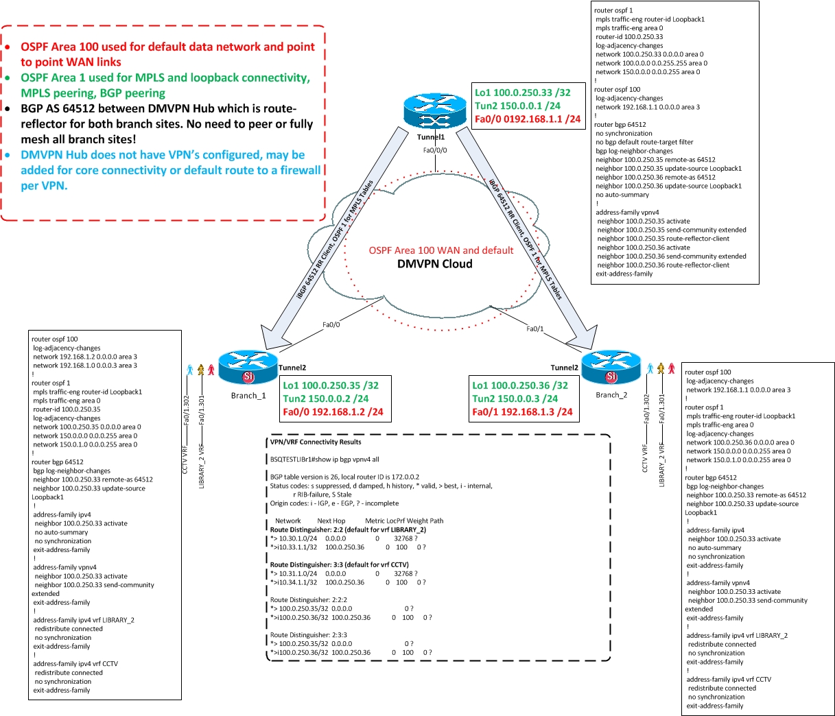
Sample configuration of a single branch below:
interface Loopback1
 ip address 100.0.250.35 255.255.255.255
 ip pim sparse-mode
!
interface Tunnel2
 ip address 150.0.0.2 255.255.255.0
 no ip redirects
 ip mtu 1368
 ip pim sparse-mode
 ip nhrp map 150.0.0.1 192.168.1.1
 ip nhrp map multicast 192.168.1.1
 ip nhrp network-id 1
 ip nhrp nhs 150.0.0.1
 ip ospf network point-to-multipoint
 ip ospf priority 0
 load-interval 30
 mpls ip
 qos pre-classify
 tunnel source 192.168.1.2
 tunnel mode gre multipoint
!
interface FastEthernet0/0
 bandwidth 10000
 ip address 192.168.1.2 255.255.255.0
 no ip redirects
 no ip unreachables
 no ip proxy-arp
 ip route-cache flow
 load-interval 30
 duplex full
 speed 100
 no cdp enable
 service-policy output WAN_DMVPN_SHAPING
!
interface FastEthernet0/1
 description to Core LAN Router
 no ip address
 no ip redirects
 no ip unreachables
 no ip proxy-arp
 ip route-cache flow
 load-interval 30
 duplex auto
 speed auto
!
interface FastEthernet0/1.301
 encapsulation dot1Q 301
 ip vrf forwarding LIBRARY_2
 ip address 10.30.1.1 255.255.255.0
!
interface FastEthernet0/1.302
 encapsulation dot1Q 302
 ip vrf forwarding CCTV
 ip address 10.31.1.1 255.255.255.0
!
router ospf 100
 log-adjacency-changes
 network 192.168.1.2 0.0.0.0 area 3
 network 192.168.1.0 0.0.0.3 area 3
!
router ospf 1
 mpls traffic-eng router-id Loopback1
 mpls traffic-eng area 0
 router-id 100.0.250.35
 log-adjacency-changes
 network 100.0.250.35 0.0.0.0 area 0
 network 150.0.0.0 0.0.0.255 area 0
 network 150.0.1.0 0.0.0.255 area 0
!
router bgp 64512
 bgp log-neighbor-changes
 neighbor 100.0.250.33 remote-as 64512
 neighbor 100.0.250.33 update-source Loopback1
 !
 address-family ipv4
  neighbor 100.0.250.33 activate
  no auto-summary
  no synchronization
 exit-address-family
 !
 address-family vpnv4
  neighbor 100.0.250.33 activate
  neighbor 100.0.250.33 send-community extended
 exit-address-family
 !
 address-family ipv4 vrf LIBRARY_2
  redistribute connected
  no synchronization
 exit-address-family
 !
 address-family ipv4 vrf CCTV
  redistribute connected
  no synchronization
 exit-address-family
More information on DMVPN and in particular 2547oDMVPN: